Family template for manholes used in Stormwater & Sewer utilitiy networks
Let's start with one of the most required families that we need when modelling a civil or infrastructure network (external MEP). It is assumed that you (readers of this article) are already familiar with the basics of Revit family creation.
Manholes. Manholes, basically drive the gravity networks like storm-water and sewer, and if you will spend some time to have that perfect family it can drive all the rest of the utility network and make everything more coordinated and emission-less.
A general rule about the manholes is that they are driven by two key Variables.
• Invert Level (IL)
and
• Cover Level (CL) commonly referred aslo as GL (Ground Level)
And as a general rule in Civil Infrastructure models or drawings your reference level is always absolute 0.00.That gives us an idea to build our family main parameters in relations to Ref.Level which is found in all family templates. It means that if you want a properly functioning positive/negative offset parameters against your Ref. Level then go to Elevation Front and create two ref planes. First ref plane above the Ref.Level and the second one below the Ref.Level. In the following illustration you can see that I used two parameters ILpos and ILneg to control the negative and positive value acceptance for my parameters.

For each parameter that you need to accept negative/positive value, you need to create an absolute value parameter. Credits for this formula go to Robert for his wonderful blogpost at DoRevit.blogspot.com.
The other factor that might be variable and might affect our manholes is the main flow Inlet and Outlet pipe diameters. When you place a connector for the pipe and assign a Radius or Dia parameter to it you can later assign some conditional formulas including your Dia parameter which will enable for example to change the chamber size as the Dia of the pipe increases or decreases.
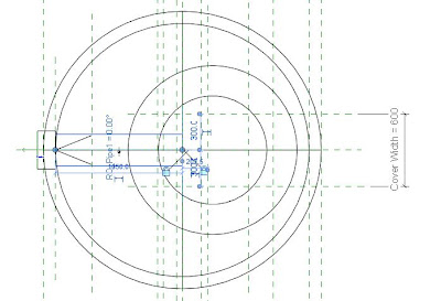
 To create a properly functioning and controlled Pipe Connector (or any Revit MEP connector) you need to first create a reference line (not a ref. plane). Which is controlled by parameters defining its horizontal and vertical positions as well as possible rotation angle within the family. You are going to place the connector on one of the ends or both ends of the ref line so place and constraint the ref line to a position where the endpoints of it are in the position of the connector(s) you want to create.

I recommend using ref line for MEP connectors they are very useful/stable and more flexible in terms of angle rotations.
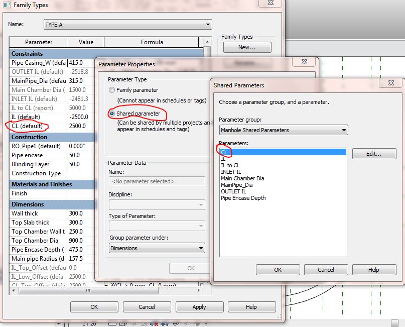
And last but not least always remember that if you are developing complex content for a specific project you must make your key parameters (constraints or construction data) as Shared Parameters in order to be able to schedule them. That will give you an extra level of control and coordination as well as the table of content. Enjoy. If you have any questions you can write to me, I'll be more than happy to address your challenges.
Manholes. Manholes, basically drive the gravity networks like storm-water and sewer, and if you will spend some time to have that perfect family it can drive all the rest of the utility network and make everything more coordinated and emission-less.
 |
| Complete Manhole Family with conditional formulas already applied. |
A general rule about the manholes is that they are driven by two key Variables.
• Invert Level (IL)
and
• Cover Level (CL) commonly referred aslo as GL (Ground Level)
And as a general rule in Civil Infrastructure models or drawings your reference level is always absolute 0.00.That gives us an idea to build our family main parameters in relations to Ref.Level which is found in all family templates. It means that if you want a properly functioning positive/negative offset parameters against your Ref. Level then go to Elevation Front and create two ref planes. First ref plane above the Ref.Level and the second one below the Ref.Level. In the following illustration you can see that I used two parameters ILpos and ILneg to control the negative and positive value acceptance for my parameters.

For each parameter that you need to accept negative/positive value, you need to create an absolute value parameter. Credits for this formula go to Robert for his wonderful blogpost at DoRevit.blogspot.com.
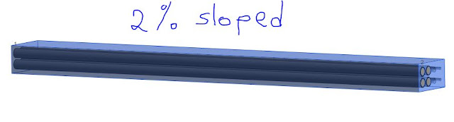
The other factor that might be variable and might affect our manholes is the main flow Inlet and Outlet pipe diameters. When you place a connector for the pipe and assign a Radius or Dia parameter to it you can later assign some conditional formulas including your Dia parameter which will enable for example to change the chamber size as the Dia of the pipe increases or decreases.


I recommend using ref line for MEP connectors they are very useful/stable and more flexible in terms of angle rotations.
And last but not least always remember that if you are developing complex content for a specific project you must make your key parameters (constraints or construction data) as Shared Parameters in order to be able to schedule them. That will give you an extra level of control and coordination as well as the table of content. Enjoy. If you have any questions you can write to me, I'll be more than happy to address your challenges.
Download the family template here. Google drive download link

Could you please share this family
ReplyDeletegreat job , thanks a lot , but still don't know how to work with -ve and +ve values for invert levels and it's relation to the body of the manhole
ReplyDelete